

PCB Post-Soldering: Process, Uses, and Quality Control
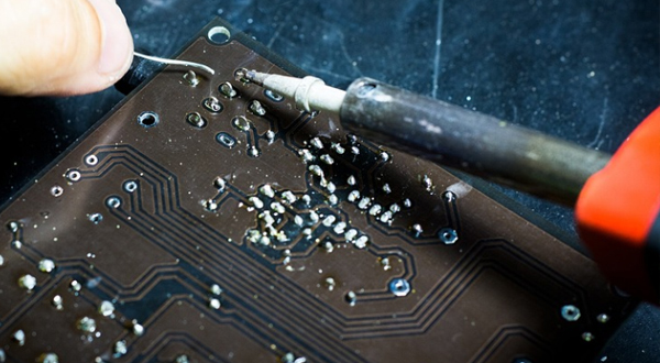
How Does Post-Soldering Fit into PCB Assembly?
During surface-mount technology (SMT) assembly, reflow soldering typically joins surface-mount components to PCB pads by melting previously applied solder paste. Wave soldering is commonly used to solder through-hole component leads on the underside of a board.
Some assemblies require a subsequent soldering operation for components or connections excluded from these processes. For example, a board may undergo SMT reflow before connectors or wires are installed and soldered separately.
In this context, “secondary soldering� or “hand soldering after reflow� can describe the operation more precisely. Hand soldering performed during initial prototype assembly is not necessarily post-soldering.
When Is PCB Post-Soldering Needed?
Components with Process or Temperature Restrictions
Some components are unsuitable for the planned reflow profile or wave soldering process. These parts may need to be installed later and soldered locally.
Localized heating still requires control. Operators must follow the component manufacturer’s soldering limits; using a soldering iron does not automatically protect a heat-sensitive component from damage.
Mixed SMT and Through-Hole Assemblies
A mixed-technology PCB may contain mostly surface-mount devices alongside a few through-hole connectors, switches, or other components. Soldering these remaining connections separately can be practical when a full wave soldering operation is unsuitable or unnecessary.
Selective soldering is another option for individual through-hole connections, with equipment and process selection depending on component characteristics and application requirements. Kurtz Ersa’s selective soldering overview
Connections Added Later in Assembly
Wires, terminals, and certain mechanical or electrical subassemblies may be attached after the main board soldering stage. Their installation sequence, accessibility, and thermal requirements determine how they should be soldered.
How Is Manual Post-Soldering Performed?
1. Verify Components and Prepare the Work Area
Before soldering, check component identity, orientation, polarity where applicable, and lead placement against the assembly documentation. Inspect the relevant pads and leads for contamination, oxidation, or damage.
Use appropriate electrostatic discharge (ESD) controls, suitable board support, and the specified solder alloy and flux. Preparation should establish that the parts are correctly positioned and suitable for soldering.
2. Control Heat Transfer and Solder Application
Use a temperature-controlled soldering station with a tip suited to the joint’s size, accessibility, and thermal mass. Keep the tip clean and properly tinned to support effective heat transfer. HAKKO emphasizes tip condition and an appropriate temperature setting as factors in reliable heat delivery. HAKKO soldering tip guidance
Heat the lead and pad sufficiently for the solder to wet both surfaces. Apply enough solder to meet the joint requirements without bridging adjacent conductors, then allow the connection to solidify without movement.
There is no universal temperature or contact time for every assembly. Process settings must account for the solder alloy, component limits, PCB construction, and joint thermal mass.
3. Inspect, Clean, and Test
After soldering, inspect for poor wetting, insufficient solder, solder bridges, disturbed joints, and thermal damage. For plated through-hole connections, assess barrel fill and other applicable acceptance requirements.
Clean residues when required by the flux system, product requirements, or subsequent processes. Perform the specified electrical or functional tests; visual inspection alone cannot confirm complete assembly performance.
Where contractually specified, use the applicable revision and product class of IPC J-STD-001 and IPC-A-610 for soldering requirements and assembly acceptance. IPC standards overview
Is Post-Soldering the Same as Rework?
Post-soldering can be a planned production step used to complete the original assembly. Rework addresses a nonconforming connection or assembly so that it meets the specified requirements.
Both may involve a soldering iron, but their purposes differ. A component intentionally installed after reflow is part of the planned assembly sequence; correcting a defective joint is rework.
Choosing the Right Soldering Method
Manual post-soldering offers flexibility for accessible connections and limited quantities. Selective or robotic soldering may be appropriate when repeatability and production volume justify automation.
The choice should consider component compatibility, joint access, thermal demands, inspection requirements, and production economics. A documented process helps ensure that secondary soldering supports the reliability of the completed PCBA.