

What Is a Rigid-Flex PCB? Structure, Applications, and Manufacturing Process
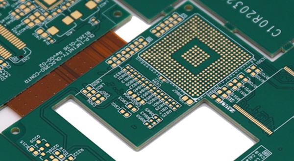
A Rigid-Flex PCB is a printed circuit board that combines rigid and flexible circuit sections into a single board structure. By integrating rigid PCB materials with flexible circuit materials, rigid-flex PCBs can provide both mechanical stability and the ability to bend or fold in designated areas.
Unlike conventional rigid PCBs that require separate cables, connectors, or flexible interconnects between different sections, a rigid-flex PCB can integrate multiple circuit sections into one interconnected assembly. This can reduce the number of connectors and soldered interfaces while making better use of limited installation space.
Key Features of Rigid-Flex PCBs
Rigid-flex PCBs offer several advantages that make them suitable for compact and space-constrained electronic products.
High-Density Integration
Rigid-flex PCBs can accommodate complex circuits within limited installation space. By integrating rigid and flexible sections into a single board, they can reduce the need for separate cables and connectors, helping to reduce overall assembly size and weight.
Improved Reliability
A rigid-flex design can reduce the number of connectors, cable connections, and soldered interfaces required between different circuit sections. Fewer interconnections can reduce potential points of mechanical or electrical failure and simplify the overall assembly.
However, the reliability of a rigid-flex PCB depends heavily on its material selection, layer structure, bend design, fabrication process, and application conditions.
Flexible Mechanical Design
The flexible sections of a rigid-flex PCB can be bent or folded within their specified design limits. This allows the circuit to follow curved or three-dimensional structures and makes rigid-flex technology particularly useful where conventional rigid boards cannot easily fit.
It is important to note that not all rigid-flex PCBs are designed for repeated dynamic bending. Some are intended only for a one-time or limited number of bends during product assembly. The required bend radius and bending conditions should therefore be considered during the PCB design stage.
pplications of Rigid-Flex PCBs
Because rigid-flex PCBs combine structural rigidity with flexible interconnection, they are used in a variety of applications where space, weight, and interconnection reliability are important.
Aerospace and Defense Electronics
Rigid-flex PCBs can help reduce wiring, connectors, and overall assembly weight in aerospace and other demanding electronic systems. Their compact structure can also simplify complex internal interconnections where installation space is limited.
Medical Equipment
Rigid-flex PCBs are used in various medical and diagnostic devices that require compact circuit layouts and reliable electrical interconnections. Their flexible sections can help the PCB conform to the mechanical structure of the equipment.
Smartphones and Consumer Electronics
Rigid-flex technology is widely used in compact consumer electronics, including smartphones and other portable devices. Flexible sections allow circuit assemblies to be routed through limited spaces or folded around mechanical structures while rigid sections provide stable mounting areas for components.
Industrial and Automotive Electronics
Rigid-flex PCBs can also be used in industrial controls, automotive electronics, instrumentation, and other applications where conventional cable-and-connector assemblies would occupy too much space or introduce unnecessary interconnection points.
How Is a Rigid-Flex PCB Made?
The manufacturing process for rigid-flex PCBs is more complex than that of conventional rigid PCBs because it combines rigid and flexible materials and requires careful control of the flexible areas.
The exact process varies according to the layer structure, material system, and design requirements, but a typical manufacturing flow may include the following stages:
1. PCB Design
The rigid and flexible sections are designed as an integrated circuit structure. Engineers determine the layer stack-up, conductor routing, bend areas, bend radius, component locations, vias, stiffeners, and mechanical dimensions.
Special attention must be given to the transition areas between rigid and flexible sections because these areas experience mechanical stress during bending and assembly.
2. Material Preparation
Rigid-flex PCBs typically use materials such as polyimide-based flexible substrates for the flex sections and epoxy-based rigid materials for the rigid sections. Coverlay, stiffeners, bonding materials, and other construction materials may also be used depending on the design.
Material selection should consider electrical requirements, thermal conditions, mechanical requirements, and the intended bending behavior.
3. Circuit Fabrication
The copper layers are processed to form the required circuit patterns. Depending on the construction, the rigid and flexible portions may undergo different processing steps before being integrated into the final board structure.
4. Drilling and Via Formation
Mechanical drilling and/or laser drilling may be used to create the required holes and microvias, depending on the board structure. Through-hole and other interconnection structures allow electrical connections to be established between different conductive layers.
5. Plating and Copper Processing
The exposed hole walls and required conductive areas are processed to establish electrical continuity between copper layers. Additional copper plating may be applied where required by the design and manufacturing specifications.
6. Lamination
The rigid and flexible layers are assembled according to the designed stack-up and laminated using appropriate bonding materials and controlled pressure and temperature.
Unlike a simple rigid PCB lamination process, rigid-flex manufacturing requires careful control of the flexible regions to prevent excessive stress, wrinkles, delamination, or other structural problems.
7. Coverlay and Stiffener Application
Flexible circuit areas are commonly protected with coverlay rather than conventional rigid-board solder mask. Stiffeners may also be added to specific flexible areas to provide additional mechanical support, particularly around connectors or component mounting areas.
8. Surface Finish and Solder Mask
The exposed copper areas are processed with the specified surface finish, such as ENIG or OSP, depending on the application and assembly requirements. Solder mask is applied to the appropriate rigid areas, while flexible sections may use coverlay or other suitable protective structures. 9. Electrical and Visual Inspection
The completed rigid-flex PCB can undergo electrical testing and visual inspection to verify circuit continuity, isolation, dimensions, surface condition, and other specified requirements.
10. Routing and Final Processing
The finished panel is routed, punched, or otherwise separated according to the required board outline. Edges and mechanical features are processed to meet the final dimensional requirements.
Rigid-Flex PCB vs. Conventional Rigid PCB
The main difference between rigid-flex and conventional rigid PCBs is their mechanical structure.
A conventional rigid PCB provides a stable, non-flexible platform for mounting electronic components, while a rigid-flex PCB combines rigid sections with flexible interconnects. This makes rigid-flex technology more suitable for products with three-dimensional structures, limited installation space, or complex mechanical requirements.
However, rigid-flex PCBs generally require more sophisticated design and manufacturing processes and can have higher fabrication costs than conventional rigid PCBs. Therefore, they are typically selected when their mechanical and integration advantages justify the additional manufacturing complexity.
Conclusion
Rigid-flex PCBs combine the structural stability of rigid circuit boards with the flexibility of flexible circuits. By integrating these two technologies into a single PCB, they can reduce connectors and wiring, improve space utilization, and support compact three-dimensional electronic designs.
Their manufacturing process involves specialized material selection, circuit fabrication, drilling, plating, lamination, coverlay or stiffener application, surface finishing, and final processing. For applications where space, weight, mechanical flexibility, and reliable interconnection are important, rigid-flex PCBs can provide an effective alternative to conventional rigid PCB and cable-based assemblies.
For manufacturers such as LJPCB, rigid-flex PCB fabrication and PCB assembly require coordinated control of PCB design, material selection, fabrication processes, and downstream assembly to ensure that the finished product meets its electrical and mechanical requirements.