

FPC vs. PCB: Key Differences, Materials, Applications & Manufacturing
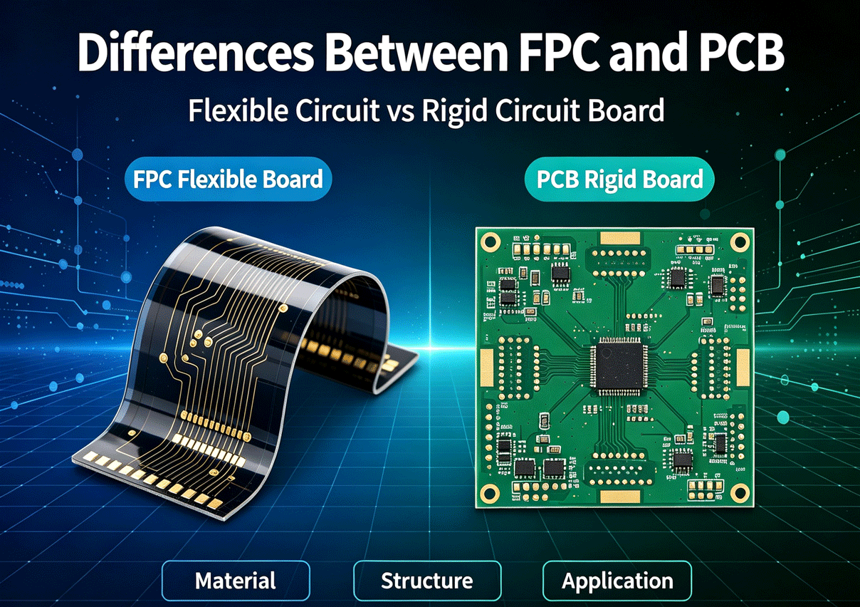
In modern electronics manufacturing, selecting the right printed circuit board structure is an important part of product design. While rigid PCBs are widely used across the electronics industry, FPCs (Flexible Printed Circuits) have become increasingly important in applications that require lightweight construction, compact packaging, or three-dimensional interconnection.
Both FPCs and rigid PCBs provide electrical interconnections between electronic components, but they differ significantly in substrate materials, mechanical properties, design considerations, manufacturing processes, and typical applications.
Understanding these differences can help engineers and product developers select the appropriate board technology for a specific application.
What Is an FPC?
An FPC, or Flexible Printed Circuit, is a printed circuit board manufactured on a flexible dielectric substrate. Polyimide (PI) is one of the most commonly used materials for flexible circuits, while other flexible dielectric materials such as PET, PEN, and LCP may also be used depending on the application.
Unlike a conventional rigid PCB, an FPC can bend or flex, making it suitable for products where components or circuit interconnections must conform to limited or three-dimensional spaces.
Flexible circuits can be manufactured as single-sided, double-sided, or multilayer structures. They may also include stiffeners, plated-through holes, blind or buried vias, and other features required by the circuit design. IPC-6013 specifically covers qualification and performance requirements for flexible and rigid-flexible printed boards.
What Is a Rigid PCB?
A rigid PCB is a conventional printed circuit board designed to maintain a fixed mechanical shape during normal operation. FR-4, a glass-reinforced epoxy laminate, is one of the most widely used materials for rigid PCBs, although other material systems are available for applications with specific electrical, thermal, mechanical, or environmental requirements.
Rigid PCBs can be manufactured in single-sided, double-sided, and multilayer configurations. Depending on the design, they may also incorporate plated through-holes, blind vias, buried vias, microvias, embedded circuitry, or metal-core structures.
Their mechanical rigidity makes them suitable for applications where the circuit board also serves as a structural platform for mounting electronic components.
FPC vs. PCB: Key Differences
Although FPCs and rigid PCBs perform similar electrical interconnection functions, their physical characteristics and design requirements are different.
1. Substrate and Material
The most fundamental difference is the substrate structure.
FPCs use flexible dielectric materials, with polyimide being a common choice. The flexible substrate allows the circuit to bend and conform to the available installation space. Rigid PCBs commonly use FR-4 or other rigid laminate systems. Depending on the application, rigid boards can also use specialized high-frequency, high-temperature, or metal-core materials.
Therefore, material selection should be based on the electrical, thermal, mechanical, and environmental requirements of the final product rather than simply choosing between “FPC material� and “PCB material.�
2. Flexibility and Mechanical Structure
The most obvious advantage of an FPC is its flexibility.
An FPC can be bent or folded to accommodate three-dimensional product structures. This can eliminate some conventional wiring and connectors while helping engineers make better use of limited internal space.
Rigid PCBs, by comparison, are designed to maintain their shape. Their rigidity provides mechanical stability and makes them suitable for applications where the board must support components and connectors in a fixed position.
However, flexibility does not automatically mean that an FPC can withstand unlimited bending. FPC design must take into account factors such as bend radius, bending direction, copper structure, material selection, and whether the application involves static bending or repeated dynamic flexing.
3. Size, Weight, and Space Utilization
FPCs are particularly useful when reducing product thickness, weight, or wiring volume is important.
Because an FPC can be routed through narrow spaces and folded around mechanical structures, it can provide a practical solution for compact electronic products.
Rigid PCBs generally require a defined mounting area and cannot conform to complex three-dimensional structures in the same way. However, rigid boards offer a broader range of mechanical and electrical design options for conventional electronic assemblies.
4. Electrical and Mechanical Design Considerations
FPC and rigid PCB designs also require different engineering considerations.
For rigid PCBs, designers typically focus on factors such as layer count, trace width and spacing, impedance control, via structures, thermal management, and mechanical dimensions.
FPC design requires these considerations as well, but also introduces additional requirements related to flexibility and mechanical stress. Trace routing through bend areas, copper geometry, stiffener placement, and bend radius can all affect the service life of a flexible circuit.
For applications involving repeated flexing, the mechanical behavior of the flexible circuit must be considered during the design stage rather than treating the FPC simply as a thinner rigid PCB.
FPC vs. PCB Applications
The choice between an FPC and a rigid PCB is largely determined by the mechanical structure and functional requirements of the end product.
Common FPC Applications
FPCs are widely used in products where compact size, low weight, or flexible interconnection is important. Typical applications include:
· Smartphones and tablets
· Wearable devices
· Cameras and optical equipment
· Display modules
· Automotive electronics
· Medical and healthcare equipment
· Compact consumer electronics
· Battery and power management assemblies
· Other applications requiring three-dimensional interconnections
FPCs are particularly useful when conventional wires, connectors, or rigid circuit boards would occupy too much space or make assembly more complicated.
Common Rigid PCB Applications
Rigid PCBs are used across a much broader range of electronic products, including:
· Computers and servers
· Industrial control equipment
· Consumer electronics
· Communication equipment
· Automotive electronics
· Power electronics
· Test and measurement equipment
· Medical devices
· Industrial automation systems
Rigid PCBs are suitable for applications requiring a stable mechanical platform for component mounting and electrical interconnection.
FPC vs. PCB Manufacturing
The manufacturing processes for FPCs and rigid PCBs share many fundamental concepts, but their materials and mechanical requirements result in important process differences. Both types of boards may involve processes such as circuit imaging, copper etching, drilling or other hole-forming processes, plating, surface finishing, solder mask or coverlay processing, and electrical testing.
However, FPC manufacturing typically uses flexible dielectric materials and may require additional processes or design considerations for coverlay, stiffeners, flexible sections, and mechanical handling.
Rigid PCB manufacturing commonly uses rigid laminate materials and may involve mechanical drilling, routing, multilayer lamination, and other processes appropriate for rigid board construction.
The exact manufacturing flow depends on the board structure, material system, layer count, feature requirements, and production specifications.
FPC and Rigid-Flex PCB: A Combination of Both Technologies
FPC and rigid PCB technology do not always have to be treated as separate solutions.
A rigid-flex PCB combines rigid and flexible sections within a single printed board structure. The rigid areas provide mechanical support for component mounting, while the flexible sections allow the circuit to bend and connect different sections of the product.
This structure can reduce the need for separate cables and connectors and can be particularly useful when multiple rigid boards need to be interconnected within a compact three-dimensional assembly.
IPC-6013 includes requirements for flexible and rigid-flexible printed boards, reflecting the established use of these structures in electronics manufacturing.
How to Choose Between FPC and Rigid PCB
The choice should be based on the actual requirements of the product rather than simply comparing the cost of the two board types.
Consider the following factors:
Product structure: If the circuit must bend or fit into a three-dimensional space, FPC may be more suitable.
Mechanical requirements: If the PCB needs to provide a rigid mounting platform for components or connectors, a rigid PCB may be preferable.
Space and weight: FPC can provide advantages where thickness, weight, and installation space are major constraints.
Bending requirements: For applications involving repeated flexing, the FPC design must be evaluated for the required bending conditions and expected service life.
Electrical requirements: High-speed, high-frequency, power, and other specialized applications may require specific substrate materials and stack-up designs regardless of whether the board is rigid or flexible.
Manufacturing requirements: Board structure, material availability, component assembly requirements, production volume, and overall manufacturing cost should also be considered.
FPC and PCB Assembly
Both FPCs and rigid PCBs can be used as substrates for electronic component assembly, but FPC assembly requires additional considerations because of the flexible substrate.
For example, FPCs may require suitable fixtures or carriers during SMT assembly to provide adequate mechanical support and maintain positional stability. Stiffeners may also be added to selected areas to improve mechanical support around component mounting or connector regions.
Rigid PCBs generally provide a stable surface for SMT and through-hole component assembly, making them straightforward to process using conventional PCB assembly equipment.
For products that combine rigid and flexible sections, the assembly process must account for both the rigid and flexible portions of the board.
FPC vs. PCB: Which One Is Better?
There is no universal answer to which technology is better.
FPC is generally a better fit when flexibility, compact packaging, low weight, or three-dimensional routing is a priority. Rigid PCB is generally more appropriate when mechanical rigidity, conventional component mounting, and a stable board structure are required.
In some products, the best solution may be a rigid-flex PCB that combines both technologies.
The correct choice should ultimately be based on the product's mechanical structure, electrical requirements, operating environment, assembly process, and manufacturing objectives.
FPC and PCB Manufacturing and Assembly from LJPCB
For electronic manufacturers, choosing the right board structure is only one part of the manufacturing process. PCB fabrication, FPC manufacturing, component sourcing, SMT assembly, and final PCBA production must work together to achieve consistent product quality.
LJPCB provides PCB manufacturing and PCBA assembly services for a range of electronic applications. Depending on project requirements, the manufacturing process can include PCB fabrication, component sourcing, SMT assembly, through-hole assembly, testing, and other production services.
By evaluating the board structure and assembly requirements at the design stage, manufacturers can select a suitable FPC, rigid PCB, or rigid-flex solution and establish a more efficient path from PCB design to finished PCBA.