

What Are the Common PCBA Soldering Methods?
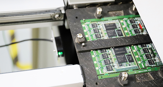
1. Reflow Soldering
Reflow soldering is mainly used for surface-mount technology (SMT) components, such as resistors, capacitors, IC chips, QFPs, BGAs, and other surface-mounted devices.
The process begins with solder paste being printed onto PCB pads through a stencil. A pick-and-place machine then accurately positions the components on the board. Next, the PCB is transferred to a reflow oven. The board passes through several controlled heating stages, typically including preheating, soaking, reflow, and cooling. During the reflow stage, the solder paste melts and wets the pads and component terminals. Once cooled, the solder solidifies and forms reliable solder joints.
Reflow soldering offers a high level of automation, high production efficiency, and consistent solder-joint quality. It is one of the most important soldering processes in SMT production, particularly for high-volume and high-density electronic assemblies.
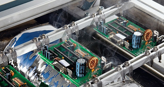
2. Wave Soldering
Wave soldering is primarily used for through-hole or dual in-line package (DIP) components, such as connectors, pin headers, transformers, relays, and large electrolytic capacitors.
Before soldering, flux is sprayed onto the underside of the PCB to clean the pads and component leads and improve solderability. The PCB then passes through a preheating zone before moving across a wave of molten solder generated above the solder pot at a controlled angle and speed. As the board passes over the wave, the molten solder contacts the through-holes, pads, and component leads to form solder joints.
Modern wave soldering machines often use a dual-wave design. The first, turbulent wave has strong penetration capability, helping the solder flow into through-holes and between closely spaced leads. The second, smoother laminar wave refines the solder-joint shape and helps reduce defects such as solder bridges and icicles.
Wave soldering is well suited to PCBs with a large number of through-hole components. It provides high efficiency and is suitable for volume production.
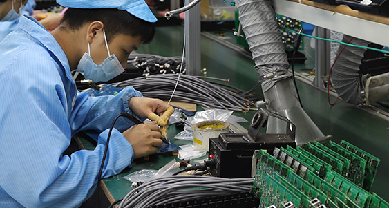
3. Manual Soldering
Manual soldering refers to a process in which operators use tools such as soldering irons, hot-air guns, solder wire, and flux to solder components by hand, perform touch-up work, or carry out repairs.
It is commonly used for prototype builds, low-volume production, component replacement, solder-joint repair, and special soldering requirements that are difficult to handle with automated equipment. For example, irregularly shaped components, large connectors, wire harness terminals, and components replaced during repair often require manual soldering.
Manual soldering requires a high level of operator skill. During the process, the soldering iron temperature, heating time, and solder amount must be properly controlled to avoid defects such as cold solder joints, solder bridges, lifted pads, and heat damage to components. Rework of high-density packages, including BGAs and QFNs, generally requires additional equipment such as a hot-air rework station, preheater, or professional rework system.
Summary
The most common PCBA soldering methods are reflow soldering, wave soldering, and manual soldering. Reflow soldering is mainly used for SMT components, wave soldering is primarily used for through-hole and DIP components, and manual soldering is generally used for prototypes, low-volume production, special components, and rework.
In actual PCBA production, one or more soldering methods may be used depending on the PCB design, component package types, production volume, and quality requirements. Selecting the appropriate process combination helps ensure soldering quality and product reliability.