

Surface Mount Technology vs. Dual In-line Package: Understanding the Differences
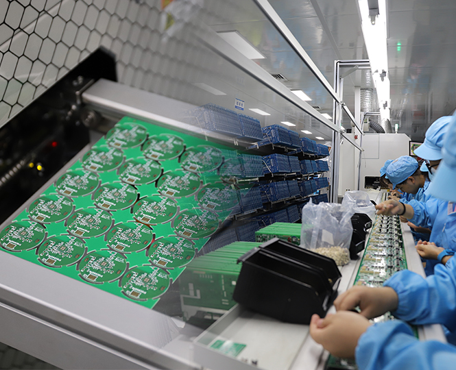
PCB assembly is a critical process in electronic manufacturing, involving the mounting and soldering of electronic components onto printed circuit boards (PCBs) to create functional electronic assemblies. During the PCB assembly process, two primary technologies are widely used: SMT (Surface Mount Technology) and DIP/THT (Dual In-line Package / Through-Hole Technology).
Although both technologies are used to assemble electronic components onto PCBs, they differ significantly in component mounting methods, production efficiency, component size, reliability, and application scenarios. Understanding the differences between SMT and DIP/THT helps engineers select the most suitable assembly method for different electronic products.
What is SMT (Surface Mount Technology)?
SMT, or Surface Mount Technology, is an advanced PCB assembly method that mounts electronic components directly onto the surface of a printed circuit board. Components used in SMT assembly are called surface mount devices (SMDs), which are typically smaller and lighter compared with traditional through-hole components.
During the SMT process, solder paste is first applied to the PCB pads through a stencil printing process. Then, automated pick-and-place machines accurately position SMD components onto the PCB surface. After that, the board passes through a reflow soldering oven, where the solder paste melts and forms reliable electrical connections between components and PCB pads.
SMT is widely used in modern electronic products such as smartphones, industrial control systems, automotive electronics, medical devices, communication equipment, and consumer electronics due to its high efficiency and excellent assembly accuracy.
What is DIP/THT (Through-Hole Technology)?
DIP/THT, also known as Through-Hole Technology, is a traditional PCB assembly method where component leads are inserted through drilled holes on the PCB and soldered on the opposite side of the board.
Unlike SMT components that are mounted on the PCB surface, through-hole components have longer leads that pass through the PCB. The soldering process can be completed through wave soldering, selective soldering, or manual soldering.
Because through-hole components provide strong mechanical bonding, DIP/THT is still widely used in applications requiring high mechanical strength and durability, such as industrial equipment, power electronics, automotive systems, and high-reliability electronic devices.
Key Differences Between SMT and DIP/THT
1. Component Mounting Method
The biggest difference between SMT and DIP/THT is the way components are mounted on the PCB.
SMT: Components are directly mounted onto the surface of the PCB using solder paste and reflow soldering technology.
DIP/THT: Component leads are inserted through PCB holes and soldered on the opposite side of the board.
SMT does not require drilling component holes, allowing for more compact PCB designs and higher component density.
SMT provides significantly higher production efficiency compared with traditional through-hole assembly.
Modern SMT production lines use highly automated equipment, including solder paste printers, pick-and-place machines, reflow ovens, SPI inspection systems, and AOI inspection equipment. This enables high-speed mass production with consistent quality.
DIP/THT assembly usually requires additional processes such as component insertion, lead cutting, and soldering. Although many factories now use automated insertion machines, through-hole assembly generally requires more processing time and manufacturing resources.
Therefore:
SMT is ideal for high-volume production and miniaturized electronic products.
DIP/THT is suitable for products requiring stronger mechanical reliability or special components.
SMT supports much smaller components compared with DIP/THT.
Since SMT components are mounted directly onto the PCB surface, manufacturers can use smaller packages such as:
0201 / 0402 chip resistors and capacitors
QFN packages
BGA packages
Fine-pitch IC components
This allows engineers to design smaller, lighter, and more powerful electronic products.
In contrast, DIP/THT components require drilled holes and physical lead spacing, which limits PCB layout density and miniaturization.
Both SMT and DIP/THT can provide reliable PCB assemblies when properly designed and manufactured. However, they have different advantages.
Advantages of SMT:
Shorter electrical connections, reducing signal interference and parasitic effects
Better performance for high-speed and high-frequency circuits
Higher component density
Suitable for compact electronic devices
Advantages of DIP/THT:
Stronger mechanical connection between components and PCB
Better resistance to mechanical stress and vibration
Suitable for large components, connectors, transformers, and power devices
For many modern electronic products, manufacturers often combine SMT and DIP/THT processes to achieve both high-density assembly and mechanical reliability.
There is no absolute answer as to which technology is better. The choice depends on product requirements, PCB design, component types, production volume, and reliability requirements.
For compact, high-performance, and high-volume electronic products, SMT assembly is usually the preferred solution.
For products requiring strong mechanical stability or large through-hole components, DIP/THT assembly remains an important technology.
In many cases, manufacturers use a mixed assembly process (SMT + DIP/THT) to combine the advantages of both technologies.